First lesson, always make sure your Arduino sinks in the breadboard!
Second lesson, there's always things that somehow didn't work:
- 3.3V -> works
- RST -> accident plugging! but it shows 3.2 V on multimeter
- 5v -> does not work
- Vin -> works but it shows 5V
And let me drill this to myself:
🚥 Series
Components that are placed in series will receive equal value of current (I), but the voltage will be divided in between them. Think of it like hiking thru 3 hills with a backpack, your energy will be depleted by the time you end the hike but the backpack (I) still weighs the same.
🚦 Parallel
Components that are placed in parallel will receive equal value of voltage (I), but the current will be divided in between them. Think of it like sending 3 friends to hike on your behalf, with the stuff in your backpack to be carried by each of them. So all of them will have consumed the same amount of energy by the time they end the hike, but the weigh of the backpacks can be divided between those 3.
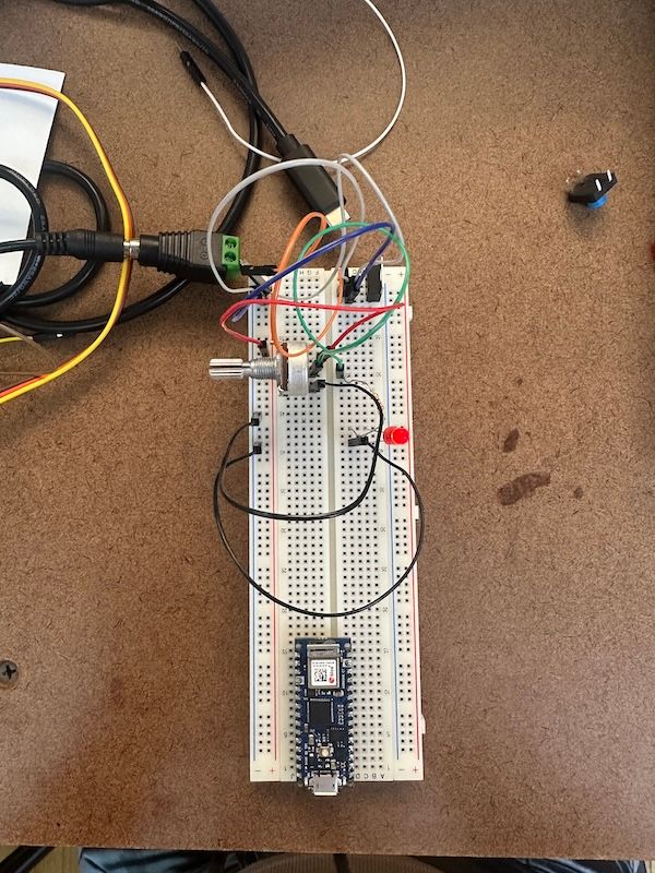
🎛️ Potentiometer
This can be something that sorta visualizes the way the electricity flows through the LED. It has the quality to escape from the binary of ON/OFF, into something that can be gradual.
Creating a circuit is very much alike to the act of coding (or maybe vice versa since physical computing came first), in a way that debugging comes very naturally to solve issues. As I read "The Rant on the Future of Interaction Design" , which argues on the pitfalls of tactile sacrifice, I found it amusing that I find debugging easier on digitals. You console.log here and there or your linter complaining to you about the problem. Maybe I've just been facing simple problems that could be solved by removing a line of code. But the thing with debugging physically, the feedback you'll get will be pretty much binary (that is, resulting in whether the system works or not), so it is difficult to analyze what actually went south.
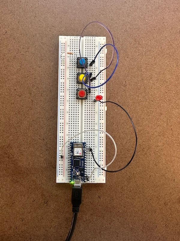
🚦 Some sparks happen, a lot of blinks and an LED baby is born...
Eyes blink -> LED lights up
I'm optimizing my school workload by connecting this week's project (from this class) with Shared Minds. For Shared Minds assignment, we have a task to interpret our consciousness on web-based interface. In this case, I'm using the interaction that I chose from the Shared Minds project (closing the eyes) as a switch to turn ON/OFF the LED.
A snippet of the "Shared Minds" project as follows, look at my eyes 👀:
For this project, the schematic and Arduino code simply follows this example. The schematic is just a closed circuit of an LED, 220-ohm resistor and Arduino Nano 33 IoT (i'm being specific with the Arduino version as later on this becomes a problem!). But, instead of connecting the positive wire to the 3.3V, I connected it to digital pin 2. The pin in some ways becomes a controlled gate to decide whether electricity flows through the LED or not.
Issues are mostly coming from the Arduino IDE. At first, I didn't specify the correct Arduino version, port, and so on. And circling back to the debugging reflection, this time the digital debugging doesn't help me at all! I have to turn to Google to find the answer to this mayhem. Shoutout to Aram who suggests that the problem is common on some Macbook versions, and he points to this solution. However, turns out that is not the case, the culprit is the fact that I have not installed the right libraries (Arduino SAMD Board) that could load Arduino Nano 33 IoT. Not just any Arduino Nano, but with 33 IoT!!! Remember!
Elizabeth Kezia Widjaja © 2026 🙂