I’ve been struggling with PCB a lot this summer and it has unconsciously influenced my ideas for other stuff, including the first class assignment for Time.
My initial idea is actually to make a purely non-electric (non-PComp) sundial ring or watch. I’ve been making some solder wire ring during the summer and thought could incorporate it as part of the aesthetic. However, this idea never even reaches sketching paper and instead I went straight to KiCad. No ideation whatsoever, it is automatic straight direction towards using light sensor to sense the shadow where the gnomon falls onto and displays the perceived time on a serial monitor or some sort of display like e-ink. I think less of the concept initially and just jumped straight to this because I’ve been trying to make an 8x8 matrix of light sensors as an experimental form of “touch screen” over the summer but it has not succeeded yet.
The Concept
As a human, you can see the time at a sundial by simply looking at the shadow where it falls onto. Your brain just does the job. Not with computers. A digital clock could possibly synchronizes to a server to get the time, or some other mechanism (i'll look for it). But my question is that can we make the digitals inquire the source of truth directly (the sun)? Just like a human can just look at the sun direction and the shadow and sort of estimate the time?
How the Digitals Keep Time
1. Hardware Clock (RTC): with quartz (when electricity hits the quarts, it vibrates at specific frequency, but this may degenerate over time), the Battery CMOS keeps the time when the computer is off.
2. Operating System Timers: ticks + interrupts. WHen computer starts, the computer asks the initial time from the Hardware Clock, but over time it will be too slow to inquire, then the computer can inquire to the local timer by sending interrupts that create x number of pulses per second and then it counts how much time has passed.
3. Internet synchronization
Now let’s begin.
Materials, very minimal!
- Phototransistor 670nm (12 pieces, 1 for each hour)
- 10k Ohm resistor (12 pieces, 1 for each phototransistor)
- Copper board for PCB milling
- Arduino Nano 33 IoT
- Analog multiplexer CD4051B (2 pieces, each has 8 reader pins, so we need 2 to cover 12 readings)
I prototyped it first on breadboard and it is proven to be working. An important note is that I'm following the Common Collector circuit (Emitter Follower).
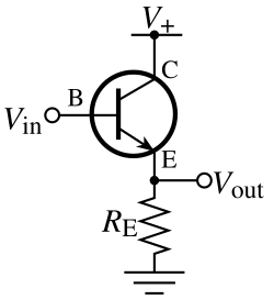
Common collector schema
The phototransistor have 2 legs: an emitter (-) and a collector (+). All of the collectors could be bussed into power rail (3.3V), while for the emitter it will be individually connected to different MUX pins. However, the emitter is also connected to a 10k Ohm resistor and to the GND, hence a pull-down resistor as a voltage divider to prevent reading floating results. These resistors can be bussed together to the GND.
Expectations of Readings:
When it is dark: The phototransistor acts like an open switch and stops conducting. The output voltage at the emitter stays at 0V.
When light shines on it: The phototransistor turns on and conducts current from the collector down to the emitter. This raises the voltage at the emitter.
The Result: The output voltage rises as the light gets brighter.
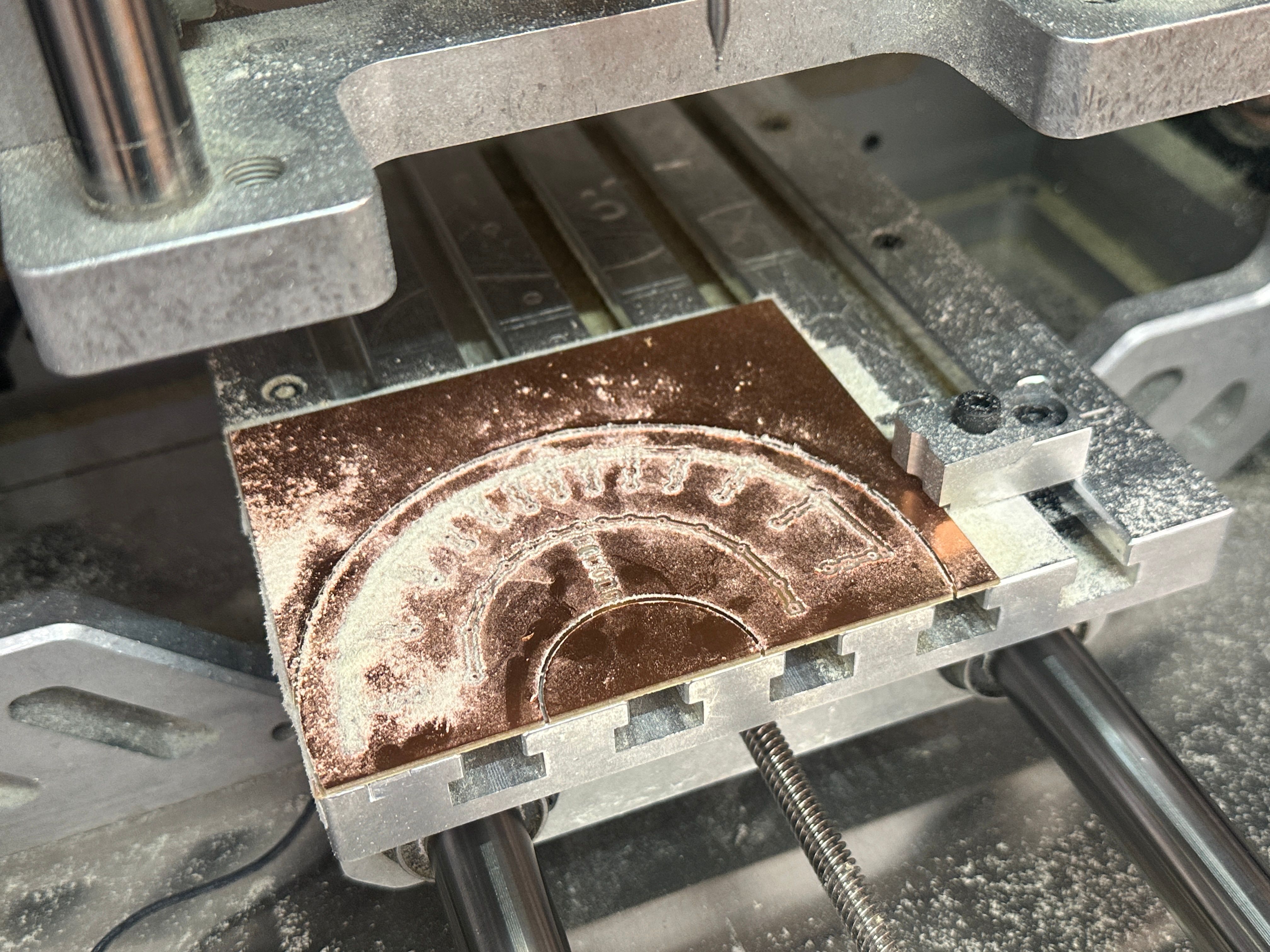
Next is the exciting part, moving on to the fabrication (milling with Bantam CNC Machine):
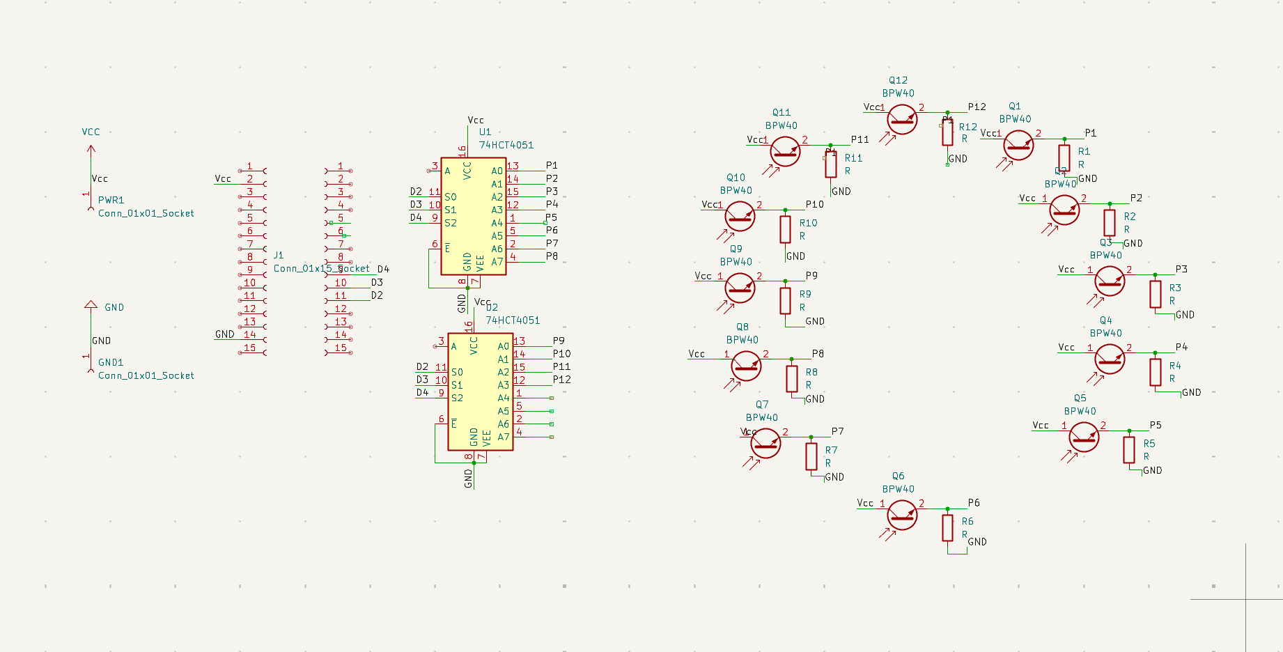
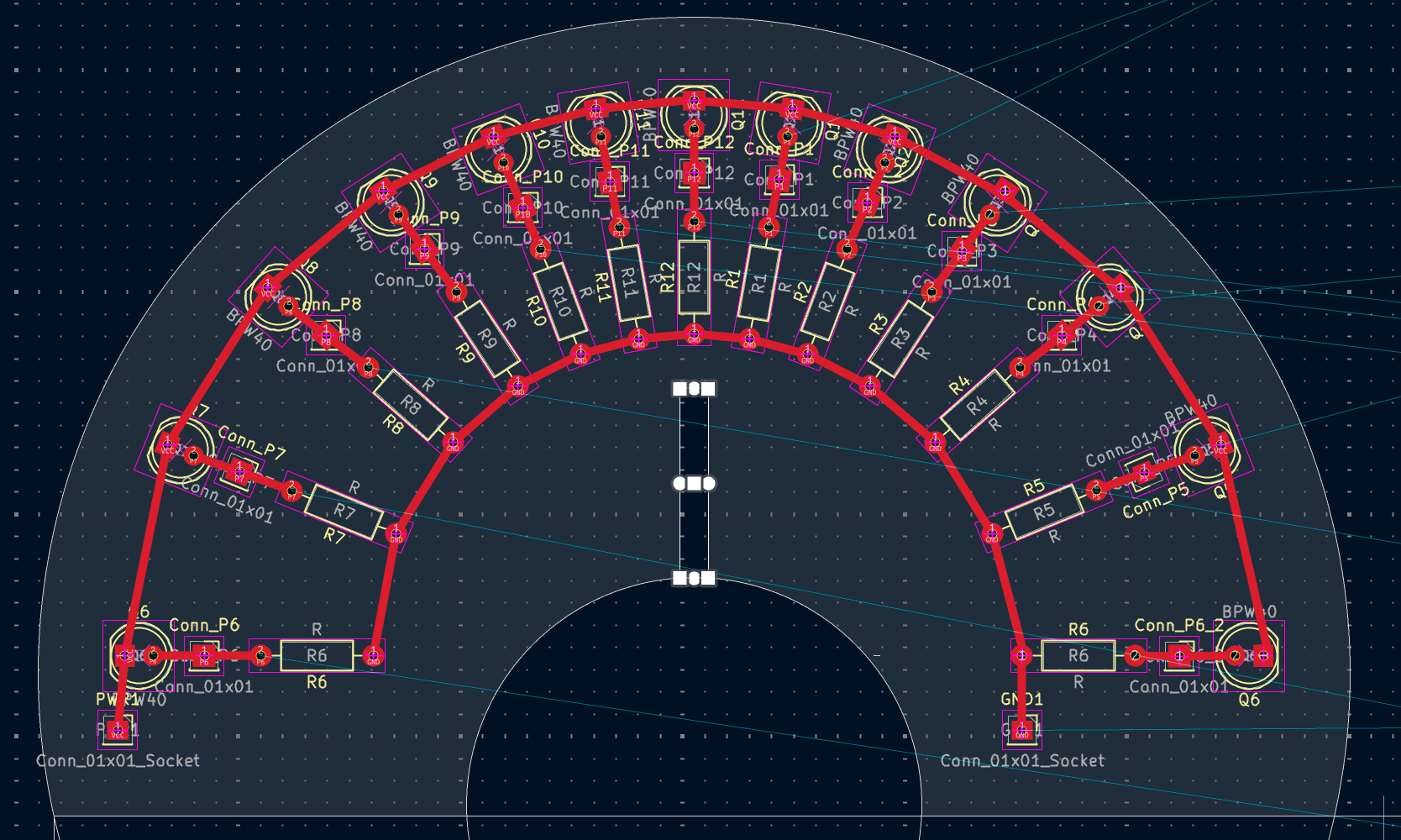
Basic schema on KiCad
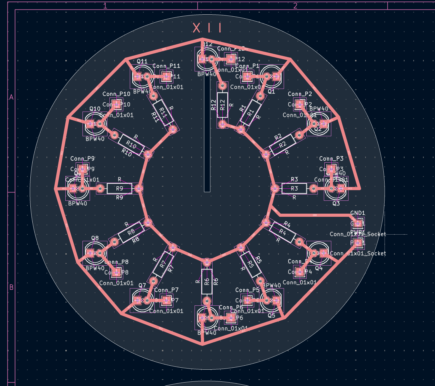
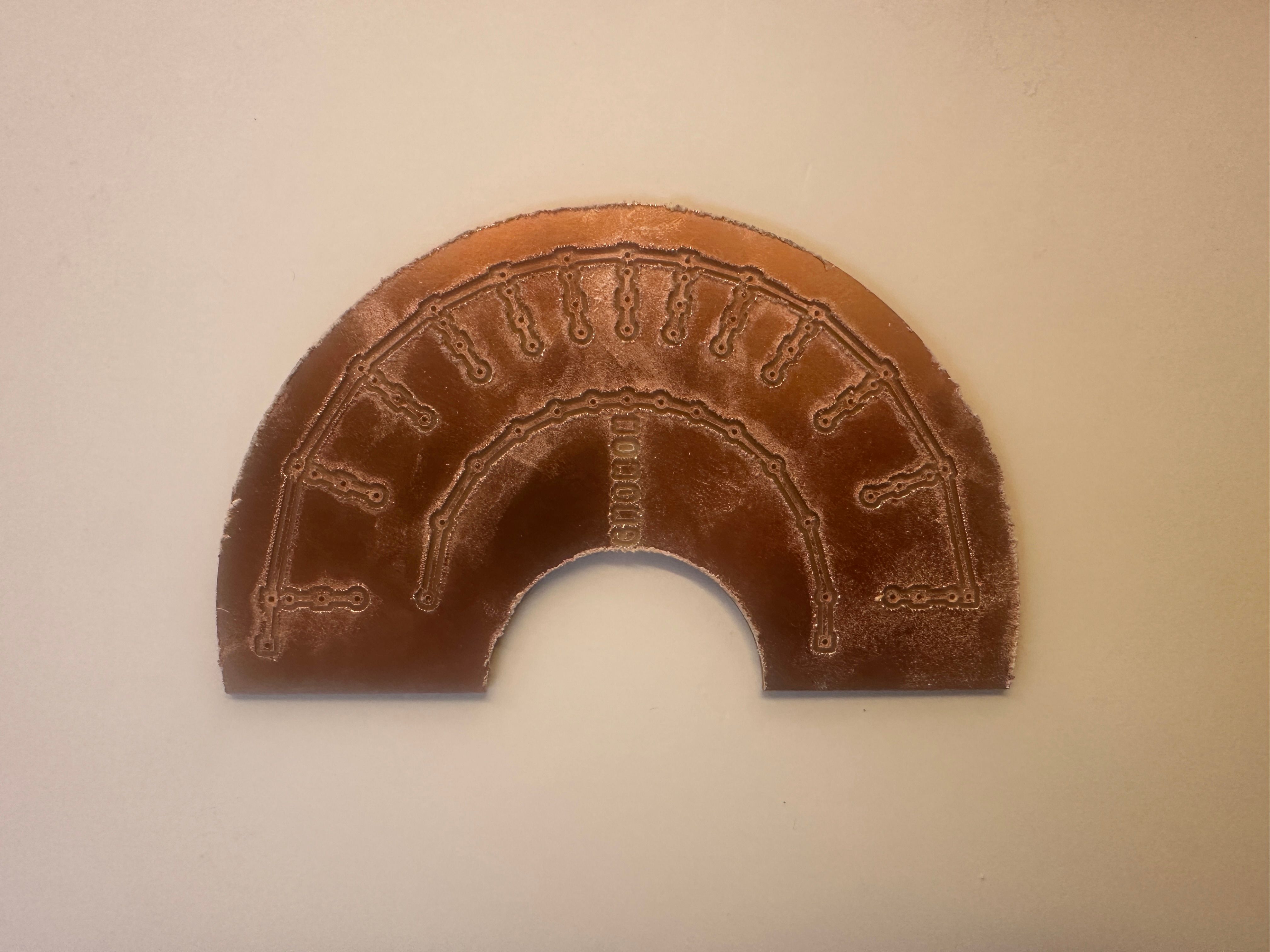
Trying as best to make it as "circular" as possible
The slit under the Hour 12 is meant for the Gnomon, which i'm not sure yet at this point what material it will be - probably just cardboard for now, it will surely be an ugly combination with the copper.
The following schema is for the second layer to align the connectors into linear formation so that it can be sunk into a breadboard easily. I'm not sure I have the time to use this method (due to the unreliability of the Bantam machine, sometimes it just fails due to little human error), I might just manually wire the connectors, then 3D print the bottom layer. The 3D print bottom layer will have 12 vertical pipes to separate the connector wiring from each other, and then it could change direction to be aligned as a linear formation so that it can be easily plugged into the breadboard or whatever is under it.
PCB Milling
The PCB milling went successful on first try, although this is possible because I have to endure a lot of failure in the summer trying it out. Ian suggested to put a wood block under the toe clamp since the copper board thickness (1.6-1.7mm) is not tall enough to reach the toe clamp. He also mentioned that the jagginess of the cut is caused by the copper board moving around when the drill bit is moving in and out because the bed where it rests is already damaged (there are a bunch of holes so the surface is not perfectly flat).
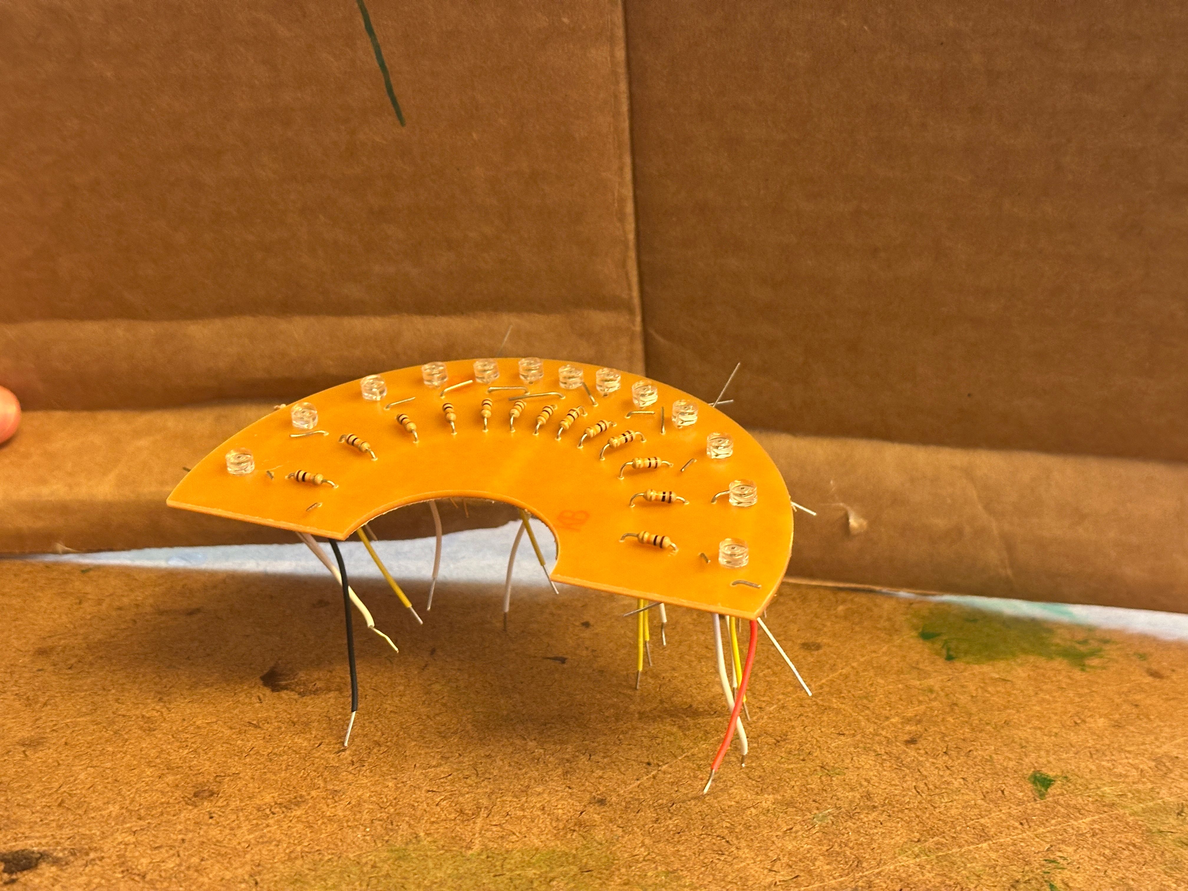
Assembling & Re-Testing
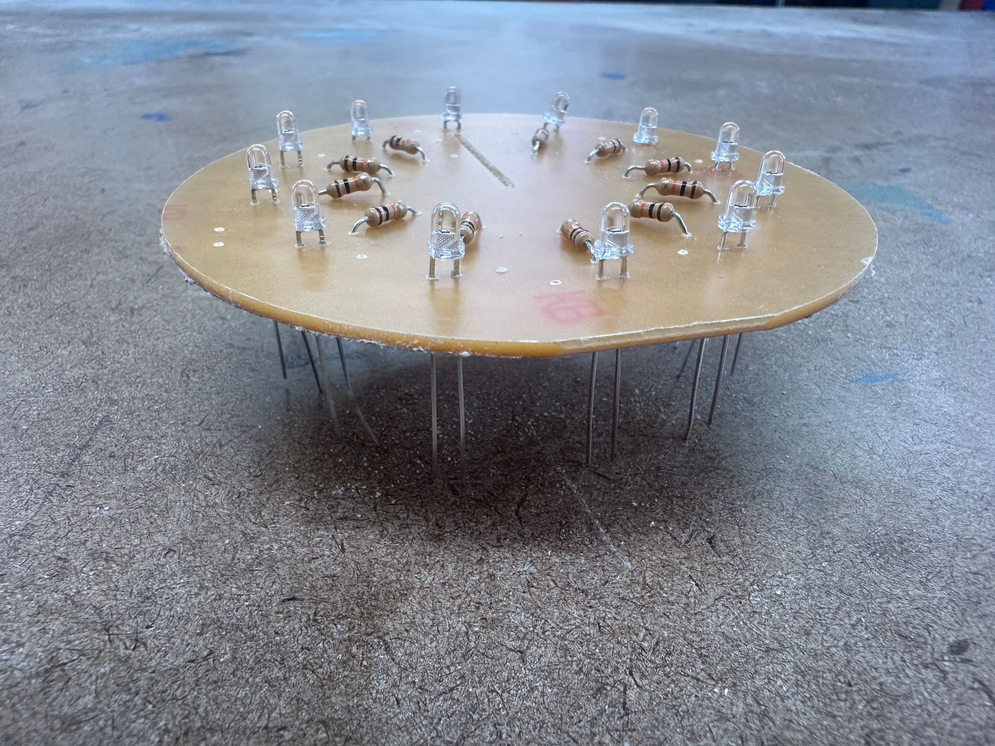
Before
Pin Datasheet
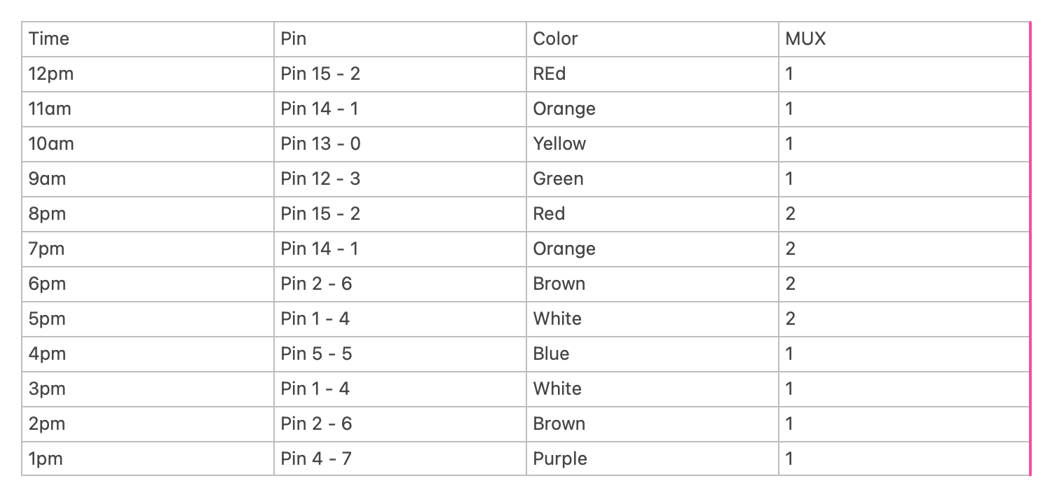
Now that it is done, don't be happy yet. Because I might mess up the soldering (I'm not very good at it). ...And sure I did, I have to play doctor on 7 out of the 12 pins. Only 5 pins give out meaningful readings on my first solder try. So apparently after my "patient check up" with multimeter (learnt that resistor legs probed at both side would not ring a continuity), some of the copper connection between the collector end and the power bus is scraped, causing disconnection. I did my surgery and it should be fixed by then. Though I'm already too tired to continue at that time. I'll continue tomorrow.
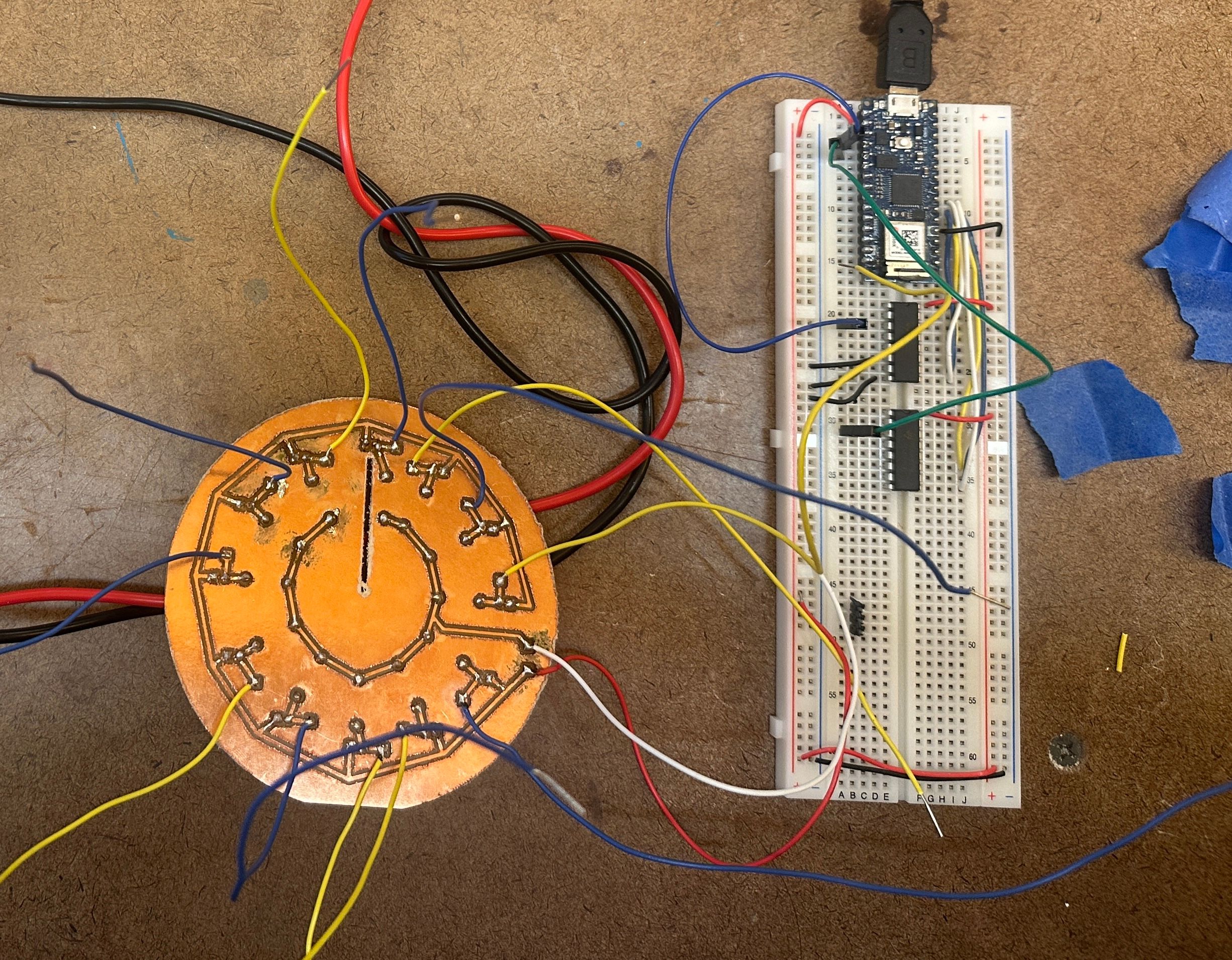
After
Gnomon
The latitude of New York City is 40.71° N. Therefore, the angle between the horizontal flat dial plate and the shadow-casting edge of the gnomon must follow that too. The gnomon must match local latitude because it has to point parallel to the Earth's invisible axis of rotation.
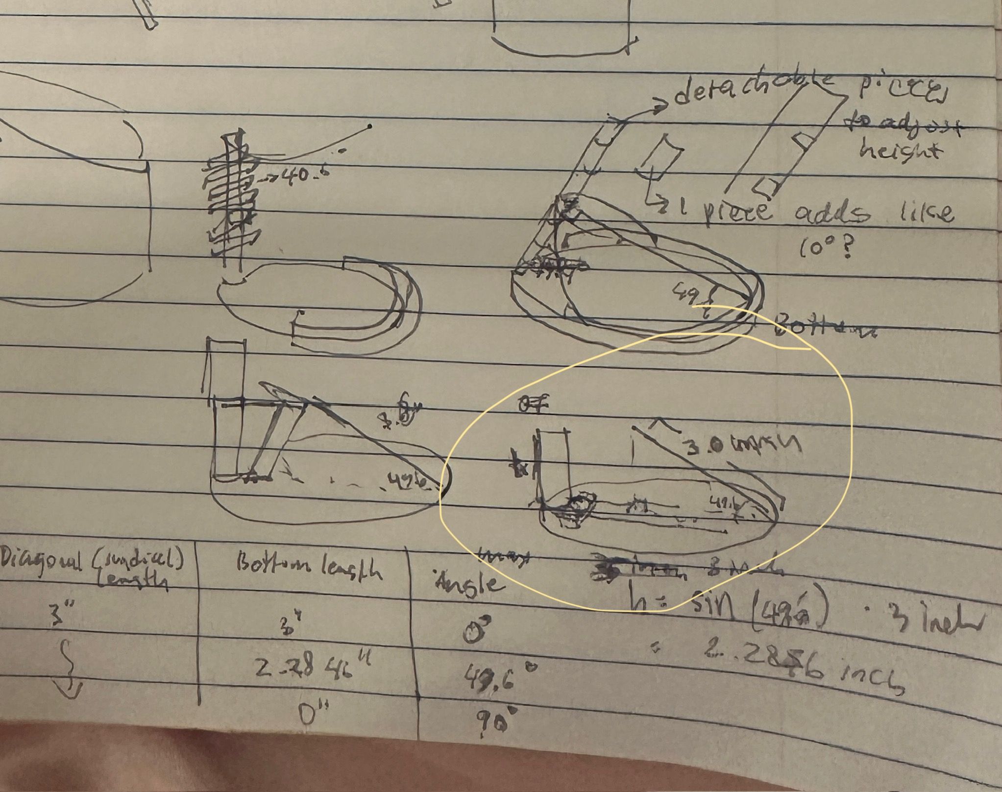
Oh shit I just realized I made the hour all at uniform angle...... I hope I can just fix it by tilting the sundial at a reversed the same axis as the latitude. Probably need to construct a tilted platform for it..... sigh. But this way it's good coz i can just use the same sundial but attach to different platform if being used at locations with different latitude. It'd be cool if the tilted housing can be adjusted angle wise as well so that it can be adapted to different place quickly without reconstructing new housing.
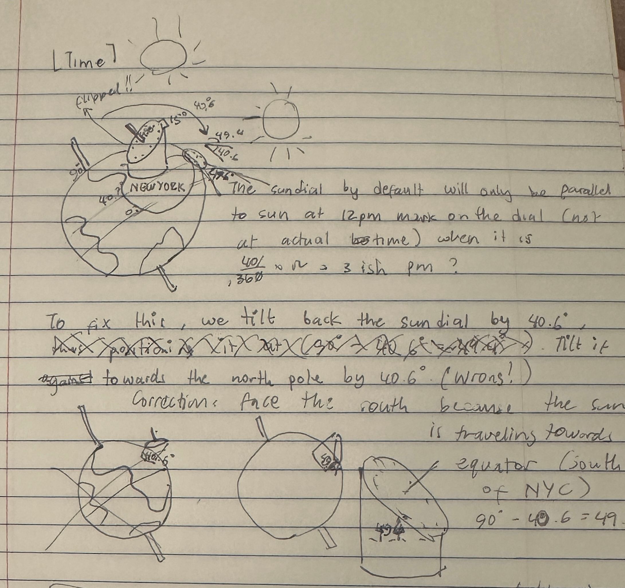
So that means the gnomon just need to be a vertical rod, fixed perpendicular in the middle of the sundial.
Another oh shit moment: if it is tilted (equatorial sundial), it needs to be divided into 24 hours instead of the current 12 hours. At this rate, I don’t think I can finish the assignment before the class time. I can probably mill the correctly angled one this monday morning but can’t solder it yet most likely.
Correction
Horizontal sundial, will not be tilted against the ground
Dynamic Bottom Support
The bottom support could have a trench that allow the vertical part where the sundial will rest move along an axis. This way we can adjust the bottom length and that will change the angle of the sundial, making this supports usage of the sundial in different latitudes.
Elizabeth Kezia Widjaja © 2026 🙂