Inspiration:
Self Portrait of Time.
Panopticon.
Surveillance / Monitoring.
Productivity tracking.
Data collection.
.... of your choice of time piece.
i'm using the escapement to automate a rubber conductive stylus to touch the capture button on a phone screen every x seconds interval.
Automaton Mechanism:
1. Deadbeat escapement drives a driver gear (40 teeth)
2. Driver gear drives the driven gear (20 teeth) - mechanical advantage doubles to be able to push and pull the next item
3. Driven gear pushes and pulls the slider piston on a linear bearing that holds a conductive rubber stylus
4. The conductive rubber stylus touches a phone screen
Math
The original layout has the big gear as the input force instead of output. If we check my previous post, I was focusing on making the RPM from the escapement wheel to be translated to just ~15s and hence the choice of having the first gear with 40 tooth and second gear half of it at 20 tooth. I forgot to calculate the mechanical advantage!
The mechanical advantage becomes ironically only 1/2 (given output / input teeth = 20 / 40). After a very urgently needed an enlightened quick consultation with Cody, I swapped them. "I wouldn't be surprised if it would just work right away" - Cody Frost. And yes it does... thank you Cody.
Rewinds back to last week Math:
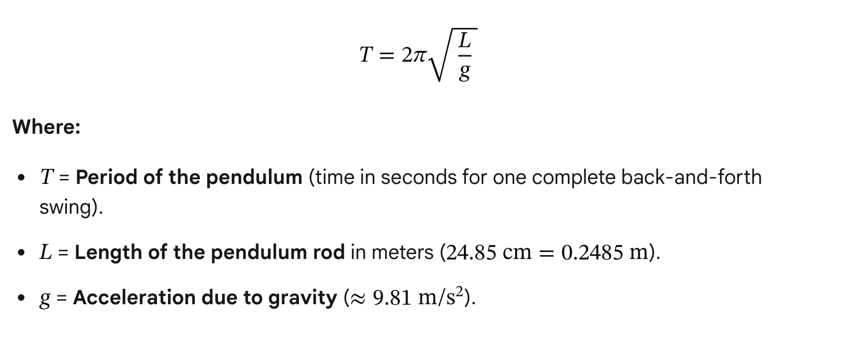
*the period is counted for both Tick + Tock together. A typical pendulum rod of 1m is often documented to generate ~1s period, but this only accounts for the "tick".
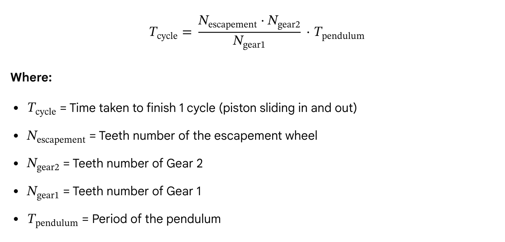
Escapement wheel teeth: 30 -> will take 30s to finish 1 round
Gear 1: 20 -> follows the escapement wheel, also 30s
Gear 2: 40 -> twice times faster than gear 1 -> 60s
Length of pendulum: 24.85cm
The pendulum period itself will roughly be ~1 second.
30 * 20 / 40 * 1 = 30s
The pen in the sliding piston will move back and forth every 15s.
Some Fusion
Steep learning curve but I feel enlightened and this is the biggest I have learnt in ITP, I feel so humbled by my spatial incapacity:
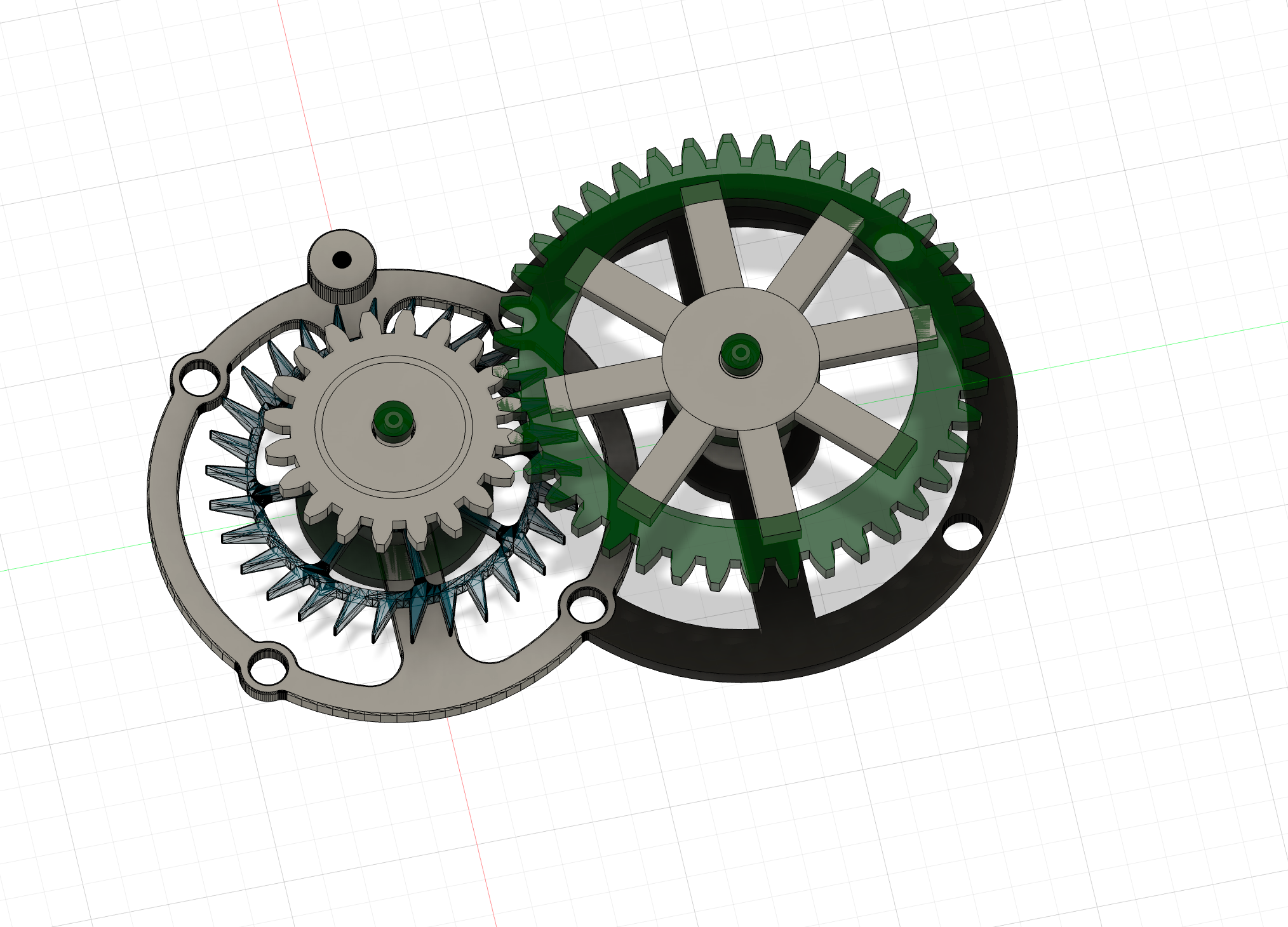
Thanks to Zekai helping me figure out how to convert mesh & make construction plane to split stuff.
Problems:
- bended pendulum rod - i had a lot of mental load learning about all of this and were really relying on Mr. Engineezy's template to at least get the escapement working and i'll just figure out my slider piston stuff. But turns out his 3D printed rod end up being bended -> i have to change it to solid aluminium / steel rod (thanks for encouragement from Fabri to do it). Found it at junk shelf. Before the realization (pre-Fabri), I still try to have some hopes with it by adjusting the weight, so when i added a little more weight it ticks some more but it still stops anyway after ~16 times ticking, and it definitely slows down before it fully stops.
BAD... it is bended and ticks unproductively (i note unproductive since it slowed down before it stops)
at least i know it will move the next gear anyway
The hollow pendulum that I picked turns out to be a little bended too lol, but the escapement works anyway, it is a perpetual motion until the weight thread finishes.
GOOD!!! Perpetual ticks (until I stop looking at it, maybe)
- I 3D printed the ball bearing on the pendulum at first lol. I don't know what ball bearing is and at first it really does not tick productively (ticks ~3 times, then it slow down and stop entirely).
- the phone may not register the touch. But it may be problem of the support case too cuz the phone right now is in the holder (so when the pencil touches it, it will vibrate for sure). The conductive rubber pen may need to be grounded too as it is a capacitive device.
- The pen slider is supposed to move around 3-4 cm as I distanced it that much from the center of the driven gear. My previous pen slider part is just a 3D printed, and it causes so much friction, it is also bended forward (as this is standing vertical) since i don't screw the holder in.
- how to connect the driven gear + slider piston set with the driver gear + escapement without weighing the escapement too much?
- the rubber tip taken from the phone stylus I bought is not strong enough to perform touch when the automaton pushes it - it may need to be grounded through my body, or may not.
Christina says i can borrow her PLA wax and we try it, it makes it slightly better but may be this is just temporary solution.
Thanks Ian for the push to buy the 10cm linear bearing from Amazon, it changes my automaton life.
PUT LINEAR BEARING ARRRGHHH
Things i broke:
- the little shaft i left out on the base where i can fix a cap on it to stop the gears from coming off
- the modified pendulum extension to be fixed to the solid aluminium rod
I printed too much I hit the limit.
Mostly because I didn't print the tolerance correctly - could have dremelled them but I found it not even and I just have this annoyance that I can't get it perfect so I re-printed it until I run out of my printing tokens.
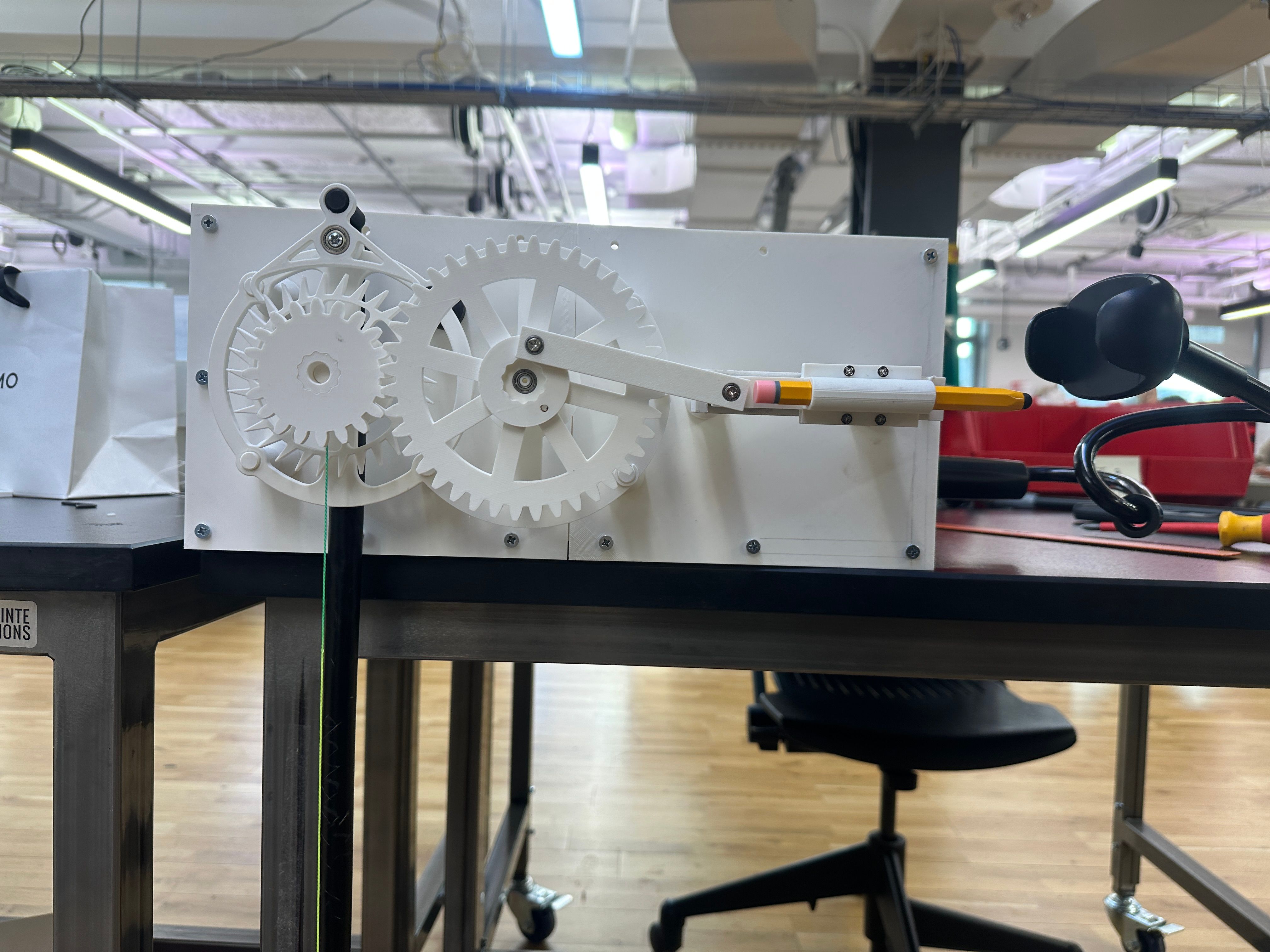
BUT IT WORKS!!! at least until the part just before it needs to touch the phone
Moving forward:
As per Phil & Ian's advice:
- replace all the shaft with aluminium / steel shaft or a bolt
- add bearing to the escapement
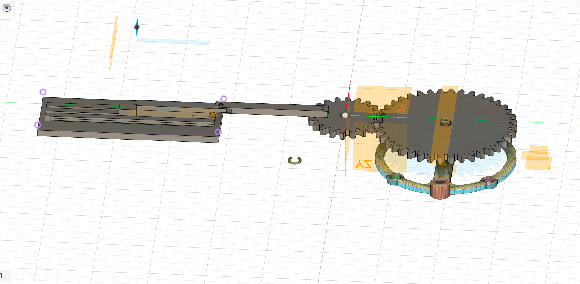
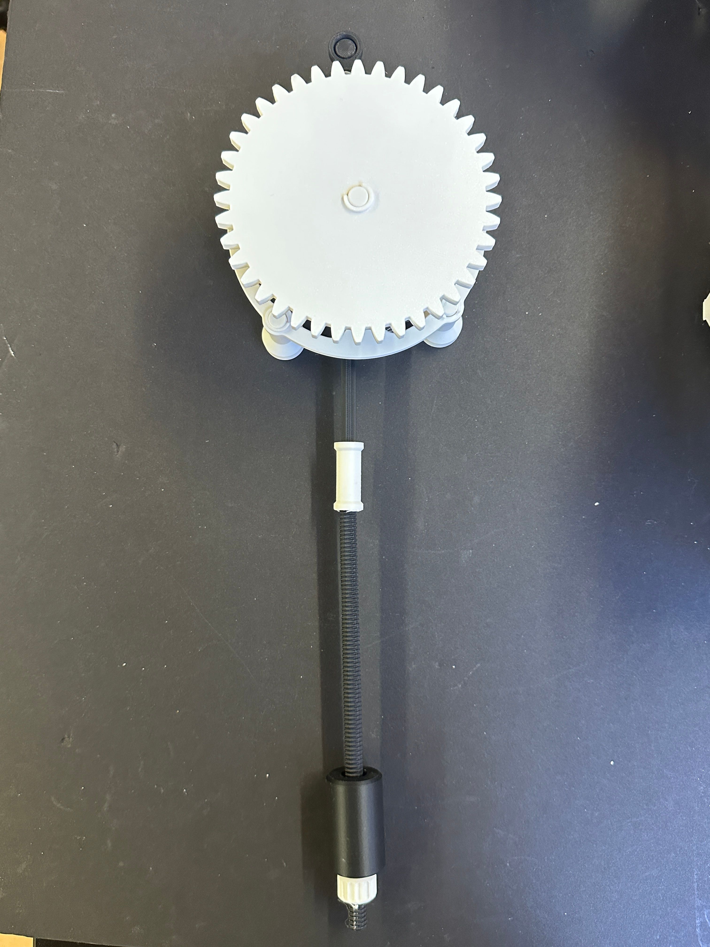
Escapement + driver gear
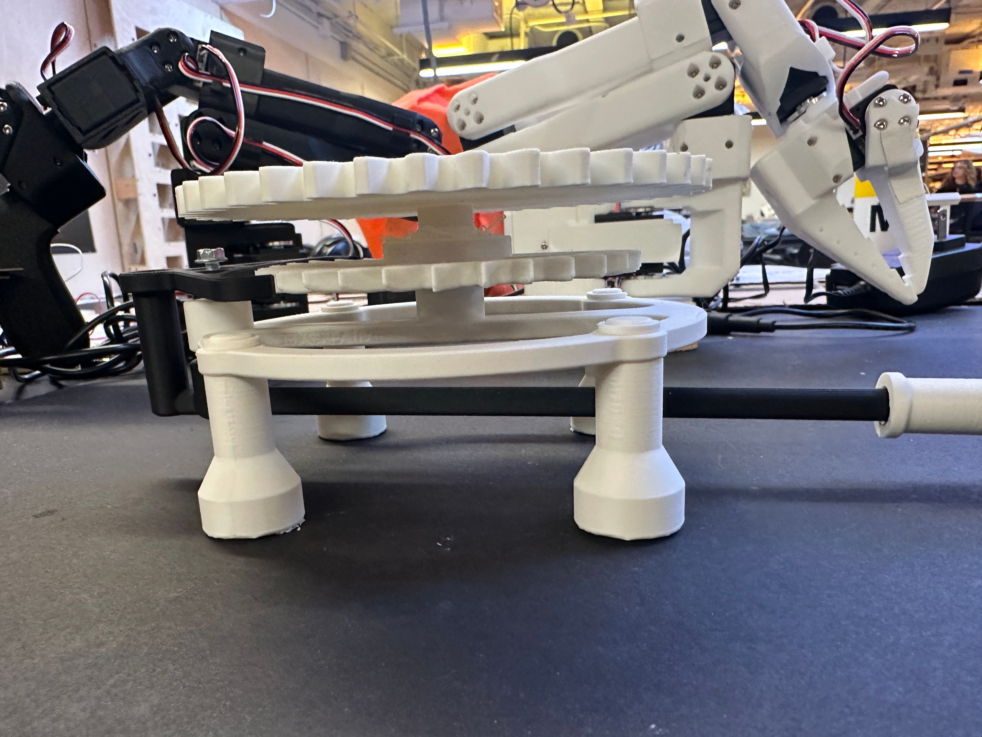
Side view showing the spool 3D-printed to connect to the driver gear
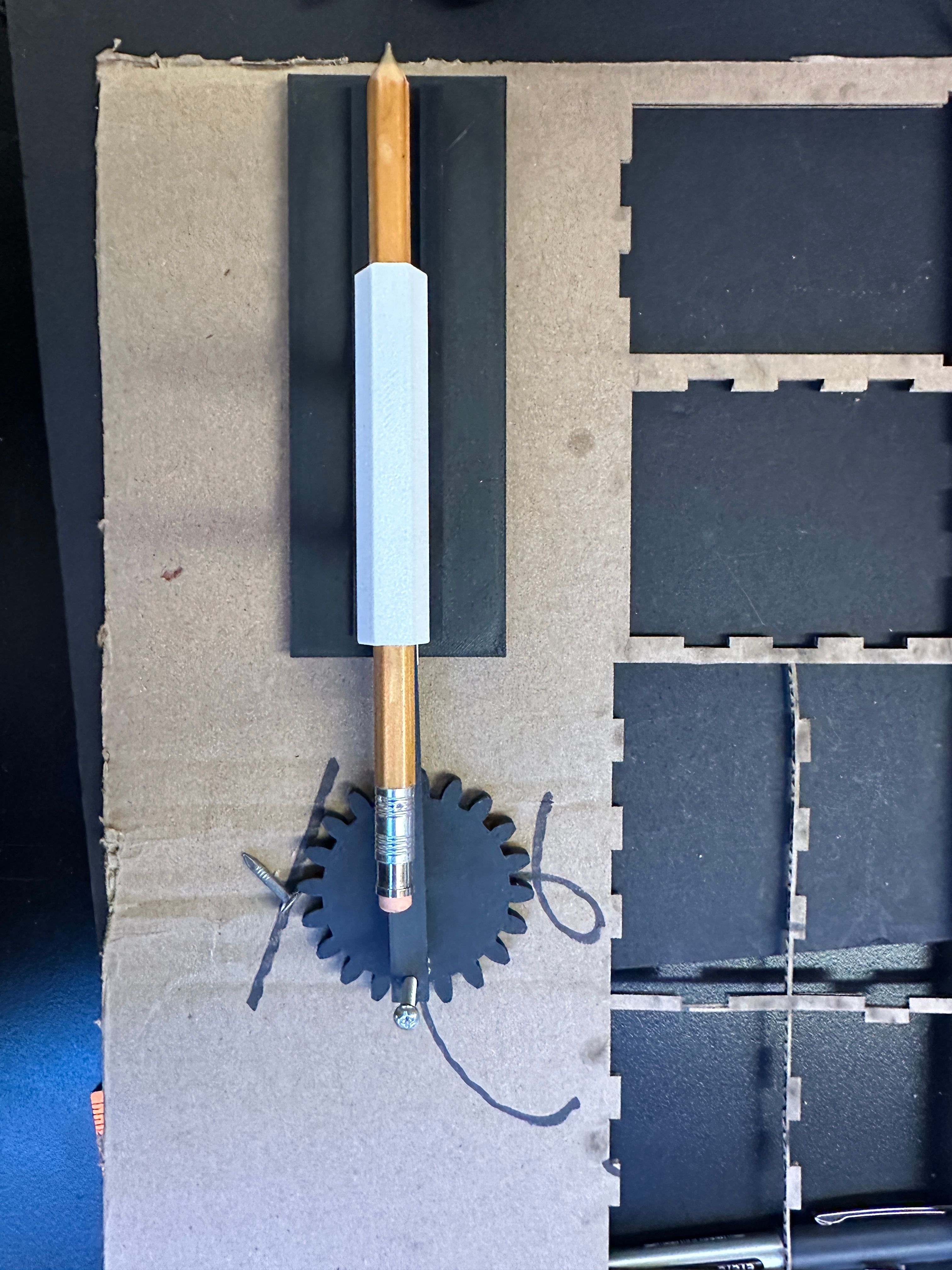
Driven gear + slider piston mechanism connected to a pen holder
Solutions
Capture
I'm faking the iPhone camera app to reduce the issues of not being able to align the conductive stylus to the camera button. Now any area on the screen when touched will be registered as capture command. A timeout is also added as the stylus lingers a little bit as it waits for the escapement to further rotate the gears, this excessive lingering causes multiple captures. Added a timeout to mitigate this issue.
latest capture demo
Elizabeth Kezia Widjaja © 2026 🙂